Willard Says……
location, location applies to situations other than real estate—such as where to locate a booster pump. Improper booster location causes lost production, inefficiency, pump breakage, blown pipelines and fittings not to mention user dissatisfaction.
See bottom of page for sketches depicting various booster pump arrangements.
Probably 25 percent of the booster pumps that I see in operation should be relocated to obtain better performance.
The dredge pump manufacturer should be the best source of information about booster pump speed and power requirements as well as location. Supply them with all the information you can about your operation and they should be able to provide guidance in these matters. Should, would, could are all expressions of hope and I hope that you get the right information from your pump manufacturer. Too often the information from the pump manufacturer is wrong because they do not know enough about their product. Or perhaps the dredge owner does not interpret the information correctly. Or maybe the pump manufacturer’s recommendations are based on bad information provided by the dredge owner. If location, pump speed or horsepower are not correct, production will suffer.
Case History
A producer decided to buy a new pump for his diesel-powered ladderpump dredge. The old pump was obsolete, inefficient and parts were hard to get. They were using a booster pump because the old ladderpump had maxed out some time previous.
After installing the new underwater pump the dredge and booster were moved to a different area of the deposit and the trouble began. Pumping with the new ladderpump proceeded as it had in the past until, without warning, the discharge pipeline plugged. It was noted that the solids in this area of the pit are quite a bit coarser than in the area mined previously. A couple of plugs later, the producer related his problem to the manufacturer of the new pump along with conditions: pipe length; pipe size; production rate; static lift; location of the booster; etc.
The pump
manufacturer responded with two recommendations.
1. Take the booster out of the
line because it was “holding
up production.” 2. Run the ladderpump
at a certain speed.
After digesting this information and suspecting it to be what it was—gobble-de-gook— he called us.
Note that this producer is a little behind the curve—he does not have a velocity meter. That makes any discussion about velocity meaningless. He has observed that the velocity is zero after the pipe plugs. Except for that condition he hasn’t a clue as to velocity.
Also note that the producer is also flying blind. He does not have a vacuum gauge on the ladderpump inlet so dredge operation is about like driving down Interstate 80 guided only by what can be seen looking in the rear view mirror. This leaves him clueless as to the rate at which solids are entering the dredge system and he does not know he has a problem until he runs into it. If he does not know the rate at which solids are entering the suction inlet, he cannot control production hence any representation made to the dredge pump manufacturer about density was a wag. Wild a** guess.
The pump manufacturer’s recommendation to take the booster pump out of the system because it interferes with production was just goofy. The new pump may well be able to support production without the aid of a booster, but to say that it interferes is preposterous. Solving a pipe plugging problem always requires more power, more pump speed and increased velocity. Plugging happens because velocity is too slow. What better way to add power and velocity than to use a booster? Even if velocity is way too high, the pipe ain’t going to plug anymore.
The pump manufacturer must have come up with the recommended pump speed by taking the vaporous conditions as supplied by the producer, consulting a pump curve of doubtful heritage and looking into their crystal ball. Any other explanation for how they came up with a precise number for pump speed has to be equally nebulous. One sure-fire pump speed would solve this producers problem given the lack of instruments; faster.
The pump manufacturer did not inquire as to whether the producer had the instruments necessary to control production nor did they recommend that he obtain them. This dredge pump manufacturer apparently has only a vague understanding of the role their product plays in a dredge system. Velocity? Density? Fine sand vs. coarse sand? Don’t worry about things like that. Just run’er fast and it will be fine. Sad.
Our recommendations to this producer? Install a velocity meter and a LADDERVAC. The latter is an electronic version of a vacuum gauge specifically designed for ladderpumps. Also read Willard Says……Velocity to learn about target velocity.
OK, how should you proceed? Start by taking the pump manufacturer’s recommendations with a grain of salt while keeping in mind the ideas outlined in this paper and Willard Says…..Booster Pumps. Observe the Booster Pump Rules. If possible use a variable speed drive. Fixed speed drives should include a means of speed reduction with a convenient way to change the ratio. Whatever it takes, a change of speed can prevent motor overload or make it possible to utilize all the available power or to avoid having to move the booster. Variable speed is good.
Consider a BIPCON (Booster Inlet Pressure CONtrol) to automatically match the speed of a diesel powered booster pump to the load under all conditions.
Most problems with a fixed-speed booster other than motor overload can be remedied by moving it closer to the dredge. Of course, very high discharge pressure may become a factor if the booster is moved too close to the dredge. Motor overload usually requires that the drive ratio be changed to slow the pump down.
| Booster Pump Rule #3 The pressure at the booster pump inlet must be POSITIVE under all pumping conditions. |
Violate this rule at your peril. Violate this rule and open the door to trouble. Violate this rule and I can see downtime and spending money in your future. Have I made myself clear?
Rule #3 means that the booster pump cannot run so fast that it develops an inlet vacuum. It also means that the dredge pump must be capable of delivering flow at a positive pressure to the booster pump inlet.
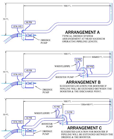
The drawings on this page depict dredge systems producing coarse sand at the rate of 400 tph. The velocity is 14 feet per second in 12-inch steel pipe and the density is 27 percent by weight. The hullpump dredges are all suction-side limited because they are maintaining an average vacuum of about 22 inches of HG—about the maximum that can be maintained. As long as all of these dredges mine from the same depth they cannot increase production because the vacuum cannot be increased.
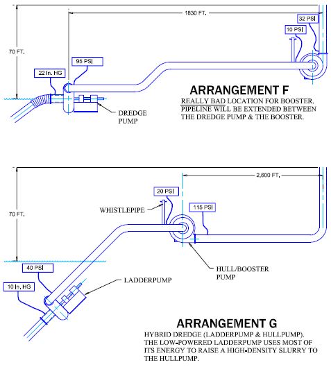
Higher production would be possible if the mining depth decreased, a
suction jet assist was installed or
the hullpump was converted to a ladderpump (Arrangement G).
See Willard Says…… papers on those subjects.
Arrangement A, shows a dredge system operating with the maximum pipeline length that one pump can service under the conditions described above. The total dynamic head (TDH) being developed by the dredge pump is found by converting the vacuum and discharge pressure to feet of head and adding them together. 22 inches of HG vacuum (24 feet of head) plus the 95 psi (219 feet of head) discharge pressure totals 243 feet of total dynamic head.
Arrangements B & C, show two recommended locations for installing a booster in the Arrangement A system. Factors such as the lay of the land, access to the booster and where pipe sections will be added determine which arrangement should be used. Note that initially the total dynamic head required to operate the system did not change after the boosters were installed. The two pumps divvy the work being done by the one pump in Arrangement A. The situation will change as pipe is added.
In Arrangement B the dredge pump is still creating the same 22 inches of vacuum (24 feet of head), however, it has been slowed down to operate at a lower discharge pressure of 45 psi (104 feet of head) so the TDH is 128 feet. The TDH developed by a booster pump is found by subtracting the pressure at the inlet from the pressure at its discharge (60 psi minus 10 psi equals 50 psi or 116 feet of TDH). Arrangement B system total TDH is 244 feet (128 feet from the dredge plus 116 feet from the booster pump).
Arrangement B suggests that the pump should be 1000 to 1200 feet from the dredge if pipe is going to be added between the booster and the discharge point. Note that both dredge and booster pumps are operating well within their capacities and have plenty of reserve to maintain flow as the pipeline length increases. If the booster is further from the dredge, the dredge will have to run with a higher TDH because Booster Rule #3 says that the inlet pressure on the booster must always be positive.
If the booster has a fixed speed power unit, adjust the speed ratio so that the inlet pressure is 10 psi or more when the system is in normal operation without overloading the motor. Ten- psi pressure at the booster pump inlet provides a margin of safety that allows for a reduction of flow from the dredge without creating a vacuum. An inlet pressure of ten psi is a suggested minimum and it can be much higher.
Arrangements C shows the booster to be about 500 feet from the dredge. Here the plan calls for pipe to be added between the dredge and the booster. Note that the TDH for this system is still 244 feet (94 feet from the dredge plus 150 feet from the booster pump).
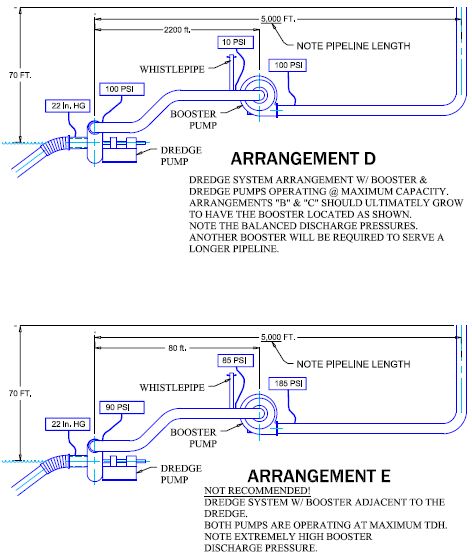
Arrangements D shows the booster pump location when the pipeline length has grown to the point where both the dredge and booster are operating at maximum rated TDH. Note that the booster will have had to be moved from the locations shown in Arrangement B or C to keep the booster discharge pressures from becoming too high. Another booster will be required to extend the pipeline beyond 5,000 feet and still maintain production.
Pressure Problems
Arrangements E is a variation of the system depicted in Arrangement D. The booster is now located adjacent to the dredge and both pumps are still developing maximum TDH to support production through 5000 feet of pipe. Theoretically this arrangement would work were it not for the dangerously high 185 psi booster discharge pressure.
Extremely high pressure makes it difficult to keep the discharge pipe joints from parting. Standard discharge sleeves are rated for a maximum pressure of 150 psi.
Plastic pipe (HDPE) must have an SDR 11 rating for use with pressures up to 160 psi. SDR 11, 14 inch OD plastic pipe has a wall thickness of 1.27 inches (Pipe OD divided by the SDR number) which leaves an ID of 11.45 inches. The wall thickness and pressure rating will decrease with wear.
I am told that the rule-of-thumb, standard dredge pump, design maximum pressure is about 220 psi. Operating at pressures near the maximum design pressure rating is dangerous.
Extremely high booster pump discharge pressure does not change the requirement that the service water pressure at the packing gland port must be at least 10 psi higher. Few service water pumps have the capacity to achieve such high pressures.
In conclusion, Arrangement E is not recommended. 125 psi is the maximum practical discharge pressure.
The maximum pipeline range for the Arrangements E dredge is probably about 2,600 feet— about the same as shown in Arrangements G.
Move the booster and keep the discharge pressures at 110 psi or less.
Arrangement G shows a common hybrid ladderpump dredge design that features a relatively low-powered underwater pump supplying a hullpump which functions as a booster pump. The ladderpump operates with a maximum TDH of 100 feet or so and functions primarily to raise high-density slurry from deep depths to the hullpump. This arrangement eliminates the suction-side limitation situation that exists on the hullpump dredge depicted in these sketches. Much of the TDH developed by the ladderpump is expended raising high-density slurry from depth to the hullpump inlet. The maximum discharge pressure developed by a hybrid dredge is limited to the TDH generated by the hullpump (booster)—120 psi or so.
Case History
Arrangement F depicts an arrangement that caused real problems for one owner. The owner maintains that the pump manufacturer recommended the location, speed, and horsepower for this fixed-speed, electric-motor- powered booster. Company electricians applied their two bits worth of ignorance when they hooked up the motor with an interlock to automatically shut the power off to the booster motor if it overloaded. The dredge could barely supply the booster pump never mind maintain a 10-psi positive pressure at its inlet.
Surges caused the booster pump to cavitate (No whistlepipe) and when the dredge sent a high-density slug up the line the under-sized electric motor overloaded and stopped. What a nightmare! After a too-long period of tribulation and finger-pointing, management bit the bullet and budgeted money to move the booster to where (Arrangement B) it should have been in the first place. Success was theirs.
Summary
Arrangement D shows the dredge/booster combination maxed out with a total of 5000 feet of pipeline. The ideal location would have the booster located about 2200 feet from the dredge to prevent the discharge pressures from exceeding 110 psi. This would require that the booster pump locations as shown on Arrangements B or C would have to changed as the pipeline length increases to avoid excessively high discharge pressure.
The right pump at the right location with adequate horsepower running at the correct speed and sporting a whistlepipe can make booster pump operation nearly trouble free. Damn near invisible.
Comment, question, criticism,
information on products mentioned? Contact willard@willardsays.com.