Willard Says……
The suction pipe conveys water and solids from its open end located some distance underwater to the dredge pump inlet. Most observers would conclude that a suction pipe is a suction pipe is a suction pipe. The question in their minds would be “What is so special about a suction pipe?”
The answer to that question has to do with whether a particular dredge is suction-side limited or not. A dredge system is said to have two sides, the suction side and the discharge side. When dredge production is limited by the rate at which solids can be raised to the pump inlet, the dredge is said to be “suction-side limited”. In other words, such a dredge could produce more if it could get more into its inlet.
Ladderpump dredges should not be suction-side limited. For that reason most of the wisdom in this paper applies only to hullpump dredges.
Since the suction pipe is the major component of the suction side of the dredge system, some study and understanding of how it works and how it can made as efficient as possible will lead to higher production.
As explained in Willard Says……Vacuum, the difference between clear water vacuum and maximum vacuum is effective vacuum. The amount of solids that can be raised to the pump is directly related to the amount of effective vacuum that is available.
Practice vacuum conservation. Horde vacuum. Use it to raise solids to the pump inlet. Hunt down and eliminate wasteful expenditures of vacuum. Vacuum is precious.
How can effective vacuum be increased? Decrease the clear water vacuum and increase the maximum vacuum.
Plastic Suction Pipe
Occasionally the question comes up as to whether or not plastic pipe can be used as suction pipe. I know of only one hullpump with a plastic suction pipe and they do not note any problems.
There are rumors that plastic pipe is slicker than steel pipe so plastic will reduce friction losses and conserve vacuum. A worthy goal founded on a shaky supposition. Published charts document the difference between water flow in shiny new plastic pipe steel pipe. Friction is less in plastic pipe when compared to steel pipe of the same inside diameter.
I ask, have you ever slid your hand along the inside of a used plastic dredge pipe? Rough, huh? How about the inside of a steel pipe immediately after flow stops? Baby’s butt smooth, right? The flow charts compare plastic, which water does not pit and corrode, to steel pipe, which water does pit and corrode. A complication arises when sand and rocks is put into the flow of water. That changes everything. The solids rough up the plastic pipe and smooth the steel. It probably safe to assume that the friction loss for the two materials is about the same for same-sized-pipes conveying slurry. In other words, I do not see any particular advantage to using plastic suction pipe.
There is, however, the matter of inside diameter where steel pipe selection is limited while plastic pipe offers a wide variety of inside diameters.
Satisfactory suction pipe function seldom requires special-size pipe. Usually, standard steel pipes will suffice. If a special, non-standard size is required, plastic pipe can probably fill the bill.
Plastic pipe (HDPE) is available in the same pipe sizes with the same outside diameters as steel pipe, however, they offer a large selection of wall thicknesses. That means that plastic pipe is specified by nominal outside diameter and a wall thickness designation called an SDR number. The wall thickness can be found by dividing the OD by the SDR number. Twelve-inch SDR 11 pipe has a 12.75” OD with a wall thickness of 12.75/11 = 1.160”. The ID is 12.75 –1.16-1.16 = 10.43”. Ten wall thicknesses are available from SDR 7.3 to 32.5 so a plastic pipe with a certain inside diameter can probably be found to satisfy a particular (and peculiar) suction pipe requirement.
Ways to Decrease Clear Water Vacuum
· MAINTAIN LOW SUCTION PIPE VELOCITY
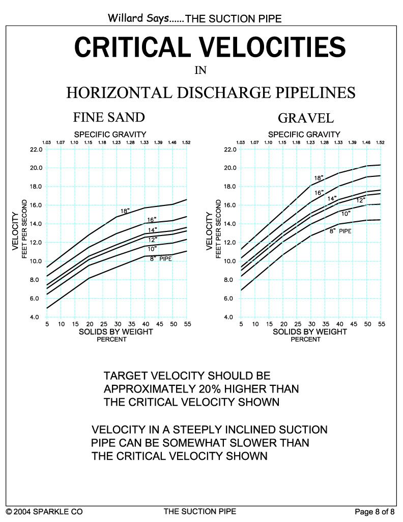
Critical velocity charts below show how the critical horizontal pipeline velocity varies with pipe size, density and particle size.
Willard Says……Using a Velocity Meter stresses the importance of determining and maintaining the target velocity—the flow rate which is about 20 percent faster than the critical velocities shown below.
A rule of thumb says that the suction pipe should be one pipe size larger than the discharge pipe and that it usually the correct arrangement. Most, but not all, standard dredge pumps feature a suction port that is one size larger than the discharge port.
Table SP1 shows a comparison of the cross sectional areas of various steel pipes and the percentage of velocity decrease in popular discharge/suction pipe combinations. For example, if a target velocity of 14 fps is maintained in a 12-inch ID discharge pipe, the velocity in the 14-inch OD suction pipe will be about 11.5 fps (14 fps discharge velocity times 0.82, the 12×14 velocity decrease factor, equals 11.5).
The target velocity should be about 20 percent higher than the critical velocity and if it is, the critical velocity should be about 11 fps. Do we have a problem if the suction pipe velocity is flowing at the critical velocity? Probably not. Here is why.
The critical velocity charts apply to horizontal pipes. Suction pipes differ from discharge lines in one important aspect—they are inclined, usually at a fairly steep angle. The critical velocity in an inclined pipe can be considerably slower than in a similar pipe lying horizontal. For this reason, the above-described 12-inch dredge system should not have a suction pipe plugging problem.
What if the suction pipe velocity is even slower than the critical velocity? What if the target velocity is 14 fps in an 8-inch discharge line? The critical velocity should be about 11fps, however, the 10-inch suction pipe velocity is only 8.8 fps (14 fps x 0.63 decrease factor). The actual velocity—8.8 fps—is considerably slower than the critical velocity of 11 fps. Will this suction pipe plug? Probably if it were horizontal, however, if is angled steeply downward odd are that it will not plug. Watch for signs of plugging and increase the target velocity if symptoms appear.
Case history:
I was asked to troubleshoot a sand and gravel dredging operation that was experiencing loss of pump prime. This 8 x10 dredge had a 50-foot-long ladder and was dredging to a depth of only 20 feet which meant that the suction pipe was not steeply inclined. They did not have a velocity meter so I installed a portable unit to better understand what was happening. Soon after they commenced pumping, the velocity slowed considerably just as I expected. When velocity fell to about 9 fps, the vacuum “locked up” and could not be reduced even after the suction had been raised to pump clear water. They related that if they did not pick up the suction, the vacuum would continue to rise until the pump cavitated and lost prime. When that happened, they had to raise the suction pipe, pull it into the bank and use a long pipe to poke a hole in the solids that were plugging the suction pipe so they could resume pumping.
They solved the problem by installing a velocity meter so that they could maintain a higher target velocity. In this case the target velocity was dependent on the critical velocity in the suction pipe not the critical velocity in the discharge pipe.
Table SP1
Steel Pipe Area Comparison
| PIPE SIZE INCHES | AREA ID SQUARE INCHES | VELOCITY SLOWDOWN PERCENT Discharge x Suction |
| 8 | 50 | |
| 10 | 79 | 8 x 10 = 63% |
| 12 | 113 | 10 x 12 = 70% |
| 14 | 138 | 12 x 14 = 82% |
| 16 | 177 | 14 x 16 =78% |
| 18 | 227 | 16 x 18 = 78% |
WATCH FOR LOW SUCTION PIPE VELOCITY
An oft-asked question at seminars is, “How far will the suction ‘pull’ solids?” The answer is usually, “About one pipe diameter.” or some other shoot-from-the-hip, without-basis-in- fact value delivered in an authoritative manner. No one ever seems to doubt the answer to this question, whatever it is. They come away from the session clutching this little nugget of useless information. It is just as well because the actual value, whatever it may be, is not important and it varies depending on conditions at the suction inlet.
The “pull distance” depends upon a.) suction pipe velocity, b.) suction inlet size, c.) suction inlet shape, d.) solids particle size distribution and e.)the availability of pumpable solids.
One hard fact rules—the velocity must be fast enough to cause pumpable solids to go with the flow, accelerate and enter the suction inlet. Velocity must increase as particle size increases. Very fine sand will move in a 5-fps flow while coarse rock may not move unless the velocity is 17 fps or more. If pumpable solids are too far from the suction inlet they will not move. If solids are near but in situ—stuck in place—they will not move readily. Peak production requires a digging device to maintain an ample supply of pumpable solids close to the suction inlet. The suction inlet must constantly be kept in near proximity to, perhaps even partially immersed in, an ample supply of pumpable solids. Whatever the “pull” distance, sufficient pumpable solids must always be close enough to readily flow into the suction inlet.
Think of your experience of attempting to vacuum-up sand or dirt crumbs with a plain-end sweeper hose. The hose inlet has to be maneuvered close enough to the particles to make them move into the hose. A sweeper will slurp up a lot of sand if the hose end is immersed in the side of the pile.
If the hose end is held too far away from particles, be they sand, small bits of paper or popcorn, they will not be swept up. Same thing happens at a dredge suction inlet.
Low suction pipe velocity is an important ingredient in the campaign to reduce friction loss in the suction pipe, but it is also important to keep the velocity fast enough to keep solids flowing in the suction pipe.
Make sure that solids are not settling out in the suction pipe by using the “principle of elasticity”. Whenever the suction is quickly raised to pump clear water, note the length of time that it takes for vacuum to fall to the normal clear water value. If the solids are all flowing in suspension, the vacuum will fall in a few seconds and it is said to be “elastic”. It is “inelastic” if it falls very slowly, an indication that solids have settled out in the suction pipe and it takes some time to get them moving. The solution is to increase the target velocity.
Another sign that the suction line is plugging due to low velocity is high vacuum that will not go away until the system is backwashed. Backwashing flushes the solids out of the pipe so that pumping can resume. If the target velocity is not increased, the suction pipe will plug again.
· USE THE CORRECT SIZED SUCTION PIPE
Most dredge pump manufacturer’s standard pumps feature a suction port that is one size larger than the discharge port, however, a few offer “square pumps” that have same-size inlet and discharge ports.
In a classic case of the blind leading the blind, some dredge builders, assuming that the “square pump” manufacturer knows what they are doing, use a suction pipe with the same diameter as the discharge pipe. In most cases this causes the velocity in the suction pipe to be much higher than necessary. The result will be needless loss due to friction and a waste of vacuum.
It is likely that the suction pipe should be the same size as the discharge pipe in the following situations:
- On some ladderpump dredges.
- On hullpump dredges with very short suction pipes.
- When the slurry includes a large percentage of very coarse gravel.
- Between the inlet of a suction jet assist and the suction inlet.
- Between a suction relief valve water inlet and the suction inlet.
· SHORT-AS-POSSIBLE SUCTION PIPE
Friction loss increases with pipe length. The ladder length should be appropriate for the mining depth and no longer.
· STRAIGHT-AS-POSSIBLE SUCTION PIPE
Elbows and suction sleeves increase head losses.
· PUMP INLET AT WATER’S SURFACE
Locate the dredge pump inlet close to the water line. Avoid wasting vacuum to raise water and solids above the water to the pump inlet.
Case history:
Fifty to sixty years ago some really lousy dredge design ideas were engineered into dredges built in-house by large sand and gravel dredging companies.
These dredges featured pumps mounted in the hull with their inlets five to seven feet above the water line. The pumps were located near the center or at the rear of the dredge hull. One company built several machines with the raised pump at the rear of the hull and a 90-degree elbow on the suction inlet so the pump discharge port could point directly out the rear of the hull.
One old timer told me that they always had problems wearing out the elbow on the discharge side of the pump so they turned the pump crossways so it discharged straight shot out the back of the dredge. No elbow to wear out. A terrible solution! The over-long pipe, suction elbow and pump height guaranteed that production would be 40 to 50 percent less than it could have been had the arrangement conformed to the suggestions listed above. The increase in effective vacuum on these dredges would have been considerable had the suction pipe been lower, shorter and straighter.
The fact that industry leaders built these abortions encouraged proliferation by copycat, do-it-yourselfers. Fortunately, the shortcomings of these dredges led to their demise. Likely the owners of these monuments to inefficiency either went broke or sold out before they did. In any event, most of them are gone now.
Ways to Increase Maximum Vacuum
Effective vacuum is the difference between clear water vacuum and the maximum or cavitation vacuum—the highest vacuum that can be maintained while pumping solids. Productive capability depends on how much effective vacuum is available. More is better. We have explored ways to reduce clear water vacuum. Now we will see what can be done to raise the maximum vacuum.
Refer to Willard Says…..Cavitation for details about Net Positive Suction Head Required (NPSHR).
NPSHR is the difference between the maximum possible vacuum (30-inches of HG) and the maximum vacuum that can be maintained without cavitating. If cavitation occurs at 21- inches of HG, the NPSHR for that pump operating under those conditions is 9 inches of HG.
The effective vacuum is 13 inches if clear water vacuum is 8 inches and cavitation starts at 21 inches. If cavitation does not occur until 25 inches of vacuum is indicated, the extra 4 inches of effective vacuum can be used to increase production.
· CHECK THE PUMP’S NPSHR
Not all pumps are created equal when it comes to NPSHR. If a hullpump dredge is suction- side limited, and they usually are, its productive capability is greater if its pump has a low NPSHR.
· KEEP THE PUMP IN GOOD REPAIR AND ADJUSTMENT
Do not allow the running gap between the suction-side liner and the impeller to open to over 0.25 inches. Gap width allows increased recirculation and power consumption. Maintain the gap at 0.125”!
· CHANGE WEAR PARTS AS NEEDED
It is common to visit a dredge and note a continuous vibration. This indicates that there is a rock lodged in the impeller or it is worn out. No rock? Change the impeller. It has worn to the point that it is out of balance and if it is worn to that extent it has also lost efficiency. It is false economy to run an impeller ‘til it look like a bird cage. The impeller is the heart of the dredge pump! It has to work good!
· MAINTAIN THE PACKING GLAND
Maintain service water flow to the packing gland sufficient to keep the pressure at the packing gland at least 10 psi higher than the dredge pump discharge pressure. Keep the packing adjusted.
· KEEP AIR OUT OF THE PUMP
Guard against leaks in that portion of suction piping that is above water. Watch for symptoms of an air leak after reassembly following parts changeout.
Summary
When is a hullpump is suction-side limited, production depends directly on the amount of effective vacuum that can be utilized to raise solids to the pump inlet. Conserve vacuum! Minimize clear water vacuum and raise the maximum operating vacuum for more production and more profit!
Comment, question, criticism,
information on products mentioned? Contact willard@willardsays.com.