Willard Says……
Booster pumps come into the dredging picture when an ever-lengthening pipeline starts to cause difficulties such as decreased production even though the dredge is thought to be performing at its maximum.
Do not conclude that you really need a booster until after you have digested and applied the ideas suggested in Willard Says……Do You Really Need A Booster.
There is no shortage of booster horror stories and many of them are true. Improperly installed and operated, booster pumps will blow up, break or otherwise come apart when subjected to pressure spikes.
Properly installed, operated and maintained, booster pumps will function without a problem and we will explore how to make that happen. Our goal is to make booster pump operation invisible.
What is a Booster Pump?
A booster pump is a dredge pump located in the discharge line between the dredge pump and discharge point. The booster pump adds head pressure (energy) to the dredge system so that maximum production can be maintained as the pipeline is extended.
Ideally, the booster pump will be the same size, model and rotation as the dredge pump to facilitate parts commonality. The booster pump can be a size larger than the dredge pump. Subject to Booster Pump Rule #1, the booster pump could be one size smaller than the dredge pump. The booster pump impeller diameter can be larger or smaller than the impeller in the dredge pump as long as Booster Pump Rule #1 is not violated.
| Booster Pump Rule #1 The openings through the booster pump impeller must be the same size or larger than the openings through dredge pump impeller |
Observing Rule #1 minimizes the chance of a rock passing through the dredge pump and lodging in the booster pump impeller.
Booster Pump Power
Booster power requirements depend on the size, make and model of the pump and on how long the pipeline will ultimately be from the booster to discharge point or to the next booster in the line.
If pipe is going to be added at the rate of only a couple hundred feet a year, perhaps a smaller, less expensive power unit can be utilized at first. A larger power unit can be installed at a later time when more power is actually needed.
The smaller power unit will do the job if the deposit is going to be depleted with the addition of only a few hundred feet if pipe.
Booster pump horsepower requirements also depends on where the booster pump is located in the discharge pipeline and whether pipe will be added between the dredge and booster or between the booster and discharge. See Willard Says……Booster Pump Location.
| Booster Pump Rule #2 Always install a whistle pipe on a booster pump inlet pipe. |
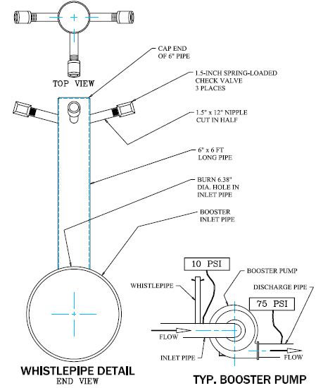
What the Hell is a WHISTLEPIPE?
Cap a 6-foot-long section of 6″ pipe and tee three 1.5″ x 6″ long NPT pipe nipples into the 6″ pipe near the capped end. Group the nipples around 180 degrees of the 6″ pipe so that they can be pointed away from pump should the check valves ever leak under pressure. Angle the nipples upward toward the capped end of the 6″ pipe so water will drain out of the check valves.
Screw 1.5″ spring-loaded check valves on each of the nipples. Install the check valves to permit flow into the 6” pipe and prevent flow out.
Install this pipe assembly, called a whistlepipe, vertically over a 6″ diameter hole in the top of the booster inlet pipe at a point near the booster pump inlet and weld in place. Do not use a tap on this pipe to gauge inlet pressure, make a separate tap on the inlet pipe.
Be sure that there is no discharge sleeve between the whistle pipe and the booster pump suction inlet! A discharge sleeve in this location will collapse under vacuum and prevent air from entering the booster pump and negate the whole purpose of the whistlepipe.
Install
pressure gauges in both the inlet and outlet pipes near the booster pump ports.
Whistlepipe Function
Booster pumps starve for liquid if the flow from the dredge pump slows too much or stops. Decreasing flow from the dredge causes a decrease in the booster pump inlet pressure and at some point the pressure will become a vacuum. The role of the whistlepipe is to allow air to enter the booster pump whenever its inlet pressure becomes a vacuum.
During normal dredge operation the check valves on the whistlepipe are held shut by the positive pressure in the booster pump inlet pipe.
The purpose of allowing air to enter the booster pump is to prevent cavitation. If low flow from the dredge continues, the booster pump will pump at the reduced rate without cavitating. When flow from the dredge increases and becomes sufficient to cause the booster pump inlet pressure to become positive, the check valves will close and the booster pump will resume normal pumping. The air bubble that was present in the booster pump will be flushed out to discharge without incident. There is not need for a vent port on the booster pump.
The presence of an air bubble in the booster pump case serves another purpose in addition to preventing cavitation. If the dredge stops pumping and then resumes—a not uncommon occurrence—the accelerating flow of slurry from the dredge will collide with the slower or stationary mass of slurry in the booster discharge pipe. The air bubble serves to cushion that collision and prevent a pressure spike. If the dredge ceases pumping, even for a considerable length of time, the air bubble in the booster pump prevents cavitation so that it can continue running for long periods of time without damage.
If air cannot enter the booster pump—no whistlepipe—it will cavitate each time the flow from the dredge falls too low. If flow remains too low or ceases, the booster pump will be traumatized by cavitation until ample flow resumes or it loses prime. When flow does resume, the accelerating mass of slurry from the dredge will collide with the stationary mass of water in the booster pump discharge pipe and create a pressure spike. Such spikes are also known as water hammer. These pressure spikes often announce their occurrence with a loud clap-of-thunder like noise and a violent shudder that may travel throughout the dredge system.
In the absence of an air bubble, high vacuum in the booster pump case and the presence of cavitation-caused bubbles of water vapor all contribute to the severity of the pressure spikes caused by the colliding slurry flows. Willard Says……Cavitation explains that the collapse of water vapor-filled bubbles in a cavitating pump is a violent occurrence by itself. The severity of pressure spikes will likely be increased when the vapor bubbles collapse simultaneously with collision of the slurry columns. If the collision is violent enough the resulting pressure spike may cause the booster pump case to break in some fashion.
Install a whistlepipe. Cushion collisions.
Booster Pump Controls
The age of telemetry is upon us. Wireless is the word. The cost and reliability of transmitting data and remote control instructions by radio make it the preferred method when hard wiring is not convenient. Dredge operation can be monitored from the office or the manager’s residence or anywhere via an online computer.
“Telemetry overdone” would describe one very elaborate booster pump control system I saw recently. The dredge operator, in addition to a full array of dredge operating instruments and controls, has two panels of booster operating instruments and controls, one for each booster in the discharge line.
Booster controls include the means to start and stop each booster pump as well as adjust their speed settings. The dredge operator is expected to monitor two panels of booster gauges, make adjustments if necessary and maintain dredge production. That is too much to ask of an operator.
It is normal for the flow rate in a dredge system to change radically for a variety of reasons. Flow changes from the dredge—velocity or density or both—affect booster pump function. If the booster is not setup to accommodate normal changes or stoppage of flow there will be problems. Asking the dredge operator to adjust booster pump speed while correcting the dredge problem that caused the booster problem makes one a little dizzy.
The thrust of this paper and Willard Says……Booster Pump Location is to suggest ways to make booster pump operation invisible so that the dredge operator can concentrate on dredge operation. Invisible in the sense that a booster pump (one or more) should operate without input from anyone from dredge startup to shutdown. That applies whether the dredge is operating or not. Input is not the same as monitoring.
More on that later. The goal is to startup the booster, assure that packing gland water flow and pressure is adequate and then begin dredging operations with assurance that whatever happens, the booster will deal with it. Some may react to this idea with disbelief. It can and is being done.
Monitoring Booster Function
Invisible booster pump operation requires telemetry of certain indicators to the dredge operator’s console:
- Diesel engine coolant temperature and oil pressure.
- Electric motor amperes.
- Booster pump accelerometer to signal excessive vibration—a sign that a rock is struck in the impeller or that the impeller is damaged.
- Service water pressure.
- Inlet pressure.
- Outlet pressure.
The alarm should alert the operator whenever one of these parameters exceeds normal operating limits. Thus notified, the dredge operator can call for help to access the problem and continue pumping long enough to flush solids out of the pipeline. The alarm should not trigger booster shutdown!
Pipeline plugging is a real danger whenever full-production pumping stops abruptly. It is your choice of course, but I believe the chances of plugging the pipeline and the penalty too great to incorporate an automatic shutdown feature in any dredge or booster control system.
The thought behind automatic shutdown is to prevent damage to some mechanical component. Seldom does that prove to be the right thing to do. Usually, clear water pumping can continue for another two or three minutes to insure that the pipeline does not plug. During that period maintenance people can ascertain the extent of the problem or if one actually exists.
Nuisance alarms are a real hazard for automatic shutdown systems. Each stoppage is an opportunity for the pipeline to plug.
Adjustable-speed drives.
Adjustable speed booster pumps, diesel or electric should have automatic controls that adjust booster pump speed as required to maintain a selected suction inlet pressure.
Electronic controls are available to control the speed of AC variable frequency or DC drives. The BIPCON (Booster Inlet Pressure CONtrol) system provides automatic speed control for diesel booster pump drives.
If flow to a booster pump equipped with a auto speed control slows down, the pump speed slows. If incoming flow ceases, booster pump speed slows to idling speed, its inlet pressure changes to a vacuum and air enters the booster pump case through the whistlepipe to prevent cavitation. The booster pump can run indefinitely in this condition without harm.
When flow from the dredge resumes, the air bubble trapped in the booster pump housing cushions the collision between the stationary slurry in the booster-to-discharge pipeline and incoming flow from the dredge pump. The air cushion prevents a high- pressure spike.
Increasing flow from the dredge causes the booster pump inlet pressure to rise to the speed control setpoint. As dredge output increases to the normal rate, the booster speed increases to maintain the setpoint pressure and normal operation resumes automatically without incident.
Booster inlet pressure speed controls match the pump speed to the load requirement and reduces pump wear and energy consumption.
The location of a speed-controlled booster pump in the discharge pipeline is not as critical as it is with fixed speed boosters. As long as the dredge is capable of delivering flow and maintaining a positive pressure at its inlet, a speed-controlled booster pump can vary its energy contribution to the dredge system from zero at idle to full power when necessary.
The combination of automatic speed control and whistlepipe makes booster operation nearly invisible. The dredge operator can do his job with little concern for what the booster is doing.
Fixed-speed Drives
Numerous fixed-speed boosters successfully follow the same procedure outlined above for variable speed pumps, however, the location of these boosters in the line is much more critical.
Whether speed-controlled or fixed-speed, boosters must always be located close enough to the pump which supplies them to maintain a positive inlet pressure during normal operation. That distance depends on the booster pump’s speed. Pump speed determines the ability of a booster to reduce the pressure in its inlet and speed determines how much energy it can supply to the dredge system.
If booster speed is too high, it may develop a vacuum in its inlet in normal operation in which case it must either be moved nearer to its supply pump or run at a slower speed. If booster speed is too slow, the amount of power it can contribution to the operation of the dredge system will be less than it could be were it to be run faster.
The critical element is to have a whistlepipe installed on the fixed-speed booster pump inlet. It is much more likely that these units will “pull” a vacuum and cavitate than speed-controlled boosters. The presence of an air bubble in the booster pump case to prevent cavitation and cushion colliding slurry flows is critical to prevent pressure spikes. With air in their gut, fixed speed pumps can also run indefinitely without harm in the absence of flow from the dredge pump even though they run at somewhat higher speeds.
Booster pump operation can be invisible.
Comment, question, criticism,
information on products mentioned? Contact willard@willardsays.com