Water and oil do not mix. How to keep that from happening.
Willard Says……
It is common practice to install a static head tank system on a dredge to pressurize oil inside submerged housings to combat the water pressure that exists outside the housing and thereby protect against water intrusion. The housing might be one containing the ladderpump shaft or the cutterdrive gearbox.
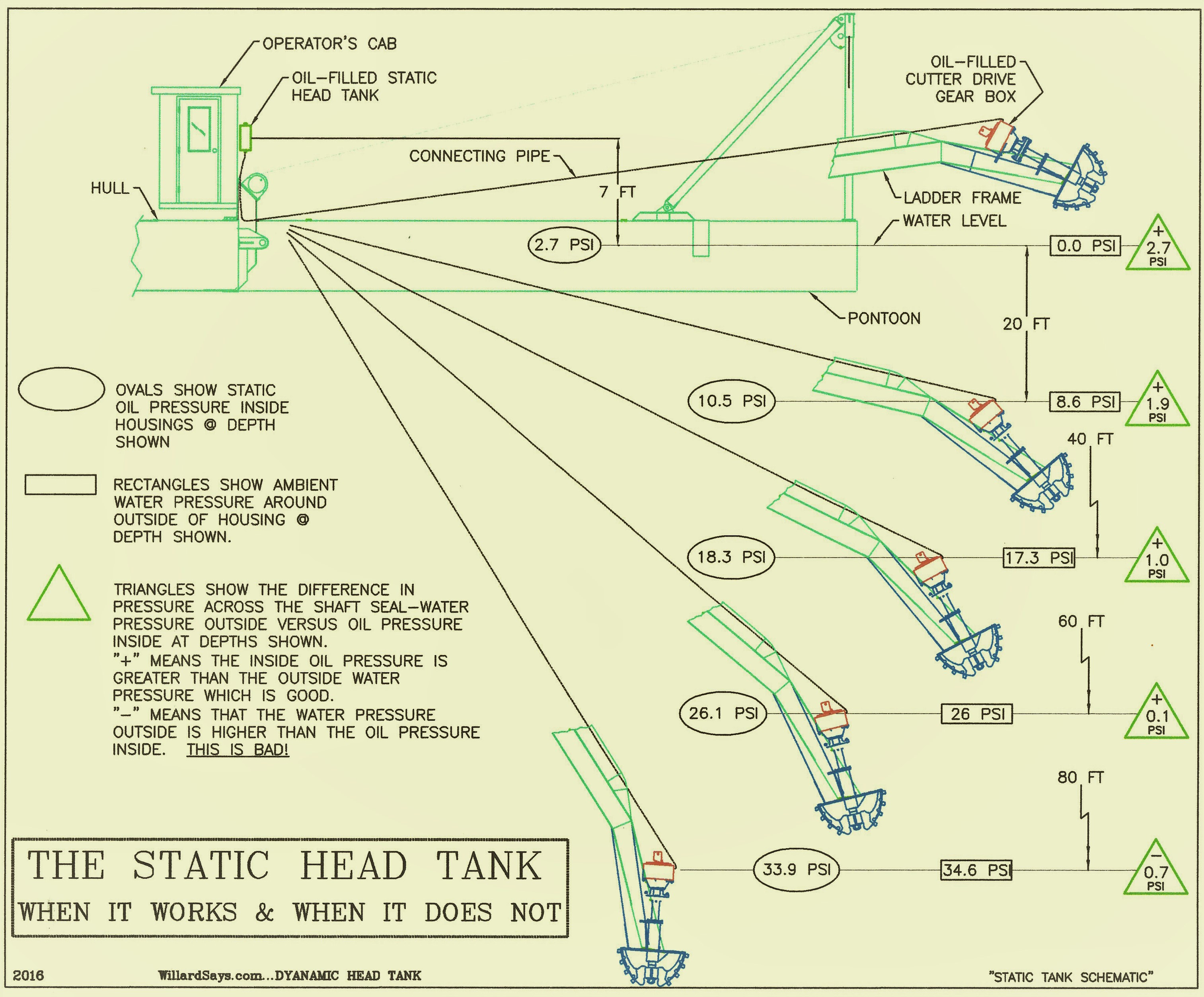
Figure #1
Figure #1 shows the general arrangement of a static head tank system on a cutterhead dredge.
The head tank is sturdy container with a capacity of one gallon or more that is fitted with breather/filler cap, sight-glass gauge and bottom port to connect to the underwater housing by means of hoses and pipes.
The head tank should be located on the dredge hull some six to ten feet above the water at a point where the operator can see the sight-glass and where it can be refilled with oil should that be necessary.
When installation is complete, the whole shebang—head tank, piping and housing—is filled with the lube oil recommended for use in the housing. It is critically important that ALL air bubbles be worked out of the connecting piping!
The pressure in the housing is dependent on the weight of the column of oil contained in the head tank and connecting piping. The pressure differential (oil pressure compared to water pressure) lessens as the depth increases because oil is 10 percent lighter than water.
The height of the column of oil contained in the piping and elevated head tank above the housing is what creates pressure on the oil in the housing. Any portion of the connecting piping that contains weightless air bubbles decreases the pressure in the housing and increases the likelihood of water intrusion.
GET THE AIR OUT!.
Figure #1 lists three pressures (all in pound per square inch, psi) at the surface and at each twenty-foot increment of depth down to eighty feet.
Oval boxes show the oil pressure inside the housing created by the column of oil in the head tank and connecting piping at each depth.
Rectangular boxes show the water pressure at each depth.
Triangle boxes show the differential pressure between interior oil and exterior water at each depth. A positive (desirable) pressure exists when the interior oil pressure is greater that the exterior water pressure.
The water pressures shown in rectangular boxes in Figure #1 at depth increments of 20 feet are calculated by dividing the depth, 20 ft for example, by 2.31 ft/psi to determine the water pressure at that depth. 20 ft/2.31 ft/psi = 8.65 psi. 2.31 ft is the height of a column of water that creates a pressure of 1 psi at its base.
The oil pressures are calculated using the depth below water plus 7 ft, the height of the head tank above water. At a housing depth of 20 feet the lighter-than- water oil column is 27 feet high and creates a pressure in the housing of 27 ft/2.57 ft/psi = 10.5 psi. 2.57 ft/psi is obtained by dividing 2.31 by 0.9 to obtain the height of oil column required to create a pressure at its base of 1 psi.
Incidentally, 231 is a handy number to keep around.
A water column 2.31 ft high creates a pressure of 1 psi at its base. 231 cubic inches equal one gallon.
The theory is that when a positive differential pressure across the seal exists, leakage, if it occurs, will result in oil leaking out of the housing instead of water leaking in thus preserving oil lubricity. Signs of an oil leak would include a surface slick and a lowering head tank oil level. Hopefully, the first sign of a problem is not component destruction due to lack of lubrication caused by water intrusion.
Operators should monitor the static tank oil level and take steps to remedy the problem immediately if the level falls. An electronic low oil-level sensor with alarm is available to relieve the operator of the oil level monitoring chore.
Occasionally, the oil level will rise and the head tank connected to a cutter drive housing will overflow. Almost always this is a sign that the hydraulic motor shaft seal has failed and hydraulic oil is flowing into the housing and up to the head tank. Repair the motor seal, install a case-drain-to-reservoir line on the hydraulic motor, drain all the oil out of the piping and housing to get the water out of the system and refill with the proper gear oil.
The pressure differentials shown in the triangle boxes in Figure #1 show that the ability of static head tank to maintain a positive pressure across the seal diminishes with depth. The ability of a static head tank system as depicted in Figure #1 to maintain a positive pressure across the seal is depleted at a depth of 55 feet or so.
An astute observer may suggest that the head tank be raised in order to increase the internal housing pressure and achieve protection at depths greater than 60 ft. That is true, however, it must be easily accessible so oil can be added when necessary and most important, the tank must be where the operator can observe the sight-glass occasionally.
Given the high cost of rebuilding a pump shaft housing or cutter drive gearbox it seems prudent to take steps keep them in “good health,” by making sure that the water stays out. This paper shows that a static head tank can do a pretty good job down to 50 feet or so, however, dredgers operating at greater depths or those who detect water in their lube oil should consider installing a Twinkle Co Dynamic Head Tank. See WillardSays….Dynamic Head Tanks. To be certain that a positive pressure is maintained within submerged housings install a Twinkle Co HEADHAWK system.
Contact willard@willardsays.com with questions, comment or criticism.