Willard Says……
This is a collection of email correspondence I have had with David over the past two years as we work together to improve the performance of his dredge. He describes the problems he was having and reached out for answers. He got useful answers and suggestions at no charge although he spent a fair amount of money to make some of the recommended improvements. He paid for those improvements in short order with the profits he enjoyed due to notable increases in production and productivity. And it made him a happy camper.
Willardsays.com is read by dredgers around the world and I receive a lot of positive comments and thank you’s, however, I am disappointed in the number of requests I get for information. I know that there are many dredgers like David who suffer problems such as those he relates below but are reluctant to ask for help. Don’t be hesitant. Perhaps you can also experience a metamorphosis. If your dredge is not producing at an acceptable rate or if the situation David was in seems familiar, contact Willardsays.com.
METAMORPHOSIS–David’s story.
(Metamorphosis: 2. A striking change in appearance, character or circumstances)
Jan. 2012
Willard,
We’ve been having trouble with wear on the inside radial surface of the back ring of our rotary cutterhead. This is the surface that faces the edge of the back plate. We’re running an AMMCO cutter and the gap between the back ring and back plate gets excessively large in a short amount of time. Most of the wear occurs on the ring, however, the back plate takes a heck of a beating and eventually wears as well. Once the gap gets large enough, rocks that cannot be crushed are causing the cutter to drag and eventually stall. Rebuilds on this particular area are being performed every 3 months. We’ve tried buildup and hard-facing both pieces and still are not having much luck getting it to last longer. Rebuilds require quite a bit of welding, fabrication, and downtime.
After much searching on the internet and some disappointing inquiries (especially from AMMCO) I’ve begun to realize this is a topic that doesn’t seem to get much attention. Surely others have run into this problem, so someone out there must have found a better way to deal with this. I can’t be the only one dredging a course deposit.
I did notice that Vosta builds a cutter with optional liners installed on the ring per customers request. However, I don’t want to buy another expensive cutter. I’m looking for some ideas that may be applied to my existing cutter; or is this something I’m going to have to live with?
Any ideas would be very much appreciated.
Thanks,
________
David,
I suppose the main reason you are having trouble finding a solution to your cutter/backring wear problem is that, as you surmise, there are no good ones.
I have a couple suggestions on how to slow the wear rate and thus the cost of maintenance.
- Rebuild the backring and backplate so that the gap is 0.25” or less. It seems that the wear rate is slower if the particles that get trapped in a pinch points are very small and easy to crush.
- Run the cutter at the slowest possible speed consistent with achieving the desired rate of production. Install a speed varying valve in your cutter drive circuit if necessary. Usually a speed of 12 to 15 rpm is sufficient if you are using three-wire positioning, keeping the cutter at the bottom of the deposit and making small sideways movements to crowd the cutter into the solids bank to provoke cave-ins.
You mention that you have a “coarse” deposit. How coarse? Can you dig down to the bottom of the deposit? Once down, can you stay down? Is your production rate satisfactory? Can you loosen material at a rate fast enough to maintain peak production? Do you have a lot of oversize? How are you keeping the oversize out of the dredge pump? Are you using a velocity meter?
Tell me a little more about your dredge and deposit. I may have some other ideas for you to consider to cut your production cost per ton.
Best regards,
________
Willard,
Thanks so much for getting back to me.
We are currently in the process of rebuilding the back ring and back plate and waiting on our local machine shop to build another cutter shaft. During dis-assembly today we found that our shaft is cracked and bent at the cutter hub. A large uncrushable rock got caught between the ring and plate, which caused the cutter to flex to the side enough to break the shaft. We’ll make sure to build up the ring and plate to get this gap around the quarter inch and try to keep it there.
Our cutter speed is about 45 rpm and has a drive hp of 40. I will slow it down some and see if I can maintain sufficient production. The hydraulic motor on the gear box is the largest c.i. we can get without major changes to the mounting housing. If slowing it down does not diminish production, then I should probably look in to getting a larger displacement motor and mounting housing to take advantage of full flow and hp.
We use four wire positioning that consists of two Gearmatic BG8’s for swing and two Gearmatic BG4’s for reversal and yaw stability.
The deposit is tightly packed with thin seams of clay and consists of approximately 20% gravel above 3/8 inch all the way up to rocks the size of small cantaloupes.
I don’t encounter very many of the large-size rocks, so I’m OK with gaining and keeping depth during dredging and oversize is kept out with bars welded between the blades. No, my production is not at peak – maybe for several minutes each hour, but definitely not at peak. Yes, I have one of your velocity meters and try to keep the velocity around 14-15 ft/s. This is tough when your suction-side limited caused by a deck-mounted pump and have frequent cave-ins. I need your CONVAC system and the pump lowered, which is the next thing getting installed during some other major changes occurring just as soon as I can get a dang stockpile big enough to shut down.
In hindsight, I wished we would’ve bought the dredge we now need with the features that would’ve provided the production I’m working towards, but we was po boys then with only a cutting torch, cracker-box welder, and gobs of ambition.
Thanks again for your help and I look forward to any other ideas you may have. If you’re ever down this way, stop in and pay us a visit. I think I share your passion about this industry.
________
January 2012
David,
I may have visited you when traveling to get Twinkle Co established in the 80’s & 90’s.
Some thoughts on your cutterhead:
DO NOT get a larger displacement hydraulic motor for your cutterhead drive!
The fact that you have power sufficient to break the cutter shaft tells me that the output torque (turning power) available from the current components (gearbox/motor/hydraulic pressure) should not be increased.
I assume that you have a hydraulic pressure gauge which indicates the operating stall pressure. I assume that you do not have a cutter speed control valve.
If you install a larger displacement motor and run at the same pressure and flow rate, the speed will decrease, however, the torque on the shaft will increase in proportion to the decrease in speed. You would need a motor with twice the displacement to cut the speed in half and the stall relief pressure would have to be reduced by half to keep from increasing torque.
A less expensive way to cut the speed is to buy a hydraulic pump with half the displacement of the present one. The rate at which oil flows to the motor determines its speed. Cutter torque is determined by the displacement of the motor and the volume of oil that flows through it.
Another way to slow your cutterhead speed and obtain speed control using the existing pump would be to install an electronic proportional control valve in place of the present cutter control valve. This valve enables the operator to control cutter speed and direction using a small dial. The new valve can be installed wherever convenient and it uses 24 VDC power. We use this valve on our new dredges to control all hydraulic functions.
You have some clay. Does your cutter basket plug up and interfere with production?
If so, think Twinkle Co’s Claymater basket to screen out oversize, dig effectively and not plug.
You are on the right track in considering a CONVAC. That would do away with interruptions caused by cave-ins and enable your operator to maintain a high vacuum (max. possible production) continuously as long as the cutter can loosen and keep an excess supply of pumpable material at the suction inlet. CONVAC would also likely make it possible to pump at a slower velocity (12 to 13 fps) which may in turn enable a higher rate of production with less energy input without fear of plugging the pipeline.
CONVAC can be installed with little downtime. The bypass pipe and hydraulics can be installed during scheduled downtime without interfering with subsequent dredge function. With those items installed, a Twinkle Co guy will come out, install the control panel, check for proper system operation and instruct in its use. Actual downtime to install would be less than one day.
Please give me particulars on the hydraulic pump that drives the cutter, make, model, speed, etc. so we can determine its output flow.
What is the cutterhead stall pressure?
How long and what inside diameter is your suction pipe?
How long and what inside diameter is your discharge pipe?
How deep below water surface do you usually dig?
What is the vertical lift water-to-discharge point?
What is your average rate of production?
As ever,
________
Willard,
Yes I agree, the torque would increase and really start tearing something up and I don’t need anything more to work on. I do have a flow control valve on the cutter system, but I haven’t been using it for speed control. It just gets used if I have to stop the cutter and knock rocks out of the teeth.
The tandem hydraulic pump was recently purchased from your company and is a GEARTEC with maximum psi of 2500 and 35 gal/min on the cutter and 20 gal/min on winches at 1500 rpm. Your guys bailed me out of a jam on this one about 2 months ago after the old Tyrone gave out. I previously said the cutter hp was 40, but I just guessed without actually running the numbers. Its probably not 40, but is somewhere in the ballpark. Cutter hydraulic pressure is set to 2400 psi max and the operating pressure frequently bumps this high during heavy digging but usually after a cave-in settles down to around 600 psi.
I’ve only experience a plugged cutter a couple of times that I can think of. I know because I am the dredge operator, builder, fixerer, and usually the one with the foulest attitude.
I would really like to install the CONVAC system now and take advantage of more consistent production until such time that I can make all the other changes.
But I have such a major design flaw with the deck-mounted pump (I’m 5 ft off the water to the suction inlet) that I’m concerned the system will not be able to compensate for the wildly fluctuating vacuum that is occurring – even pumping fresh water. And yes, I have replaced the suction hose thinking that the liner had come loose, but that wasn’t it. It’s probably due to the ridiculous plumbing of the suction pipe on the front of the pump in an effort to get the suction hose closer to the ladder pivot point. Also, maintaining an average production (around 180- 220 tons/hr. based on measuring the stockpiles) puts the vacuum at 24 and 25 in. Hg. This is causing considerable hammering in the pump. So, as you are probably estimating, there are some serious problems with this set-up.
The inside diameter of the suction pipe is 10 3/4 in. minus the wall thickness of 3/8 in, so around 10 in.
Discharge pipe ID is 8 5/8 in. minus the 3/8 in. wall thickness for some new pipe, but most is worn thinner than this. It’s probably on an average around 8 1/8 in. However, I’m in the process of changing all steel pipe with flanged discharge hose having an ID of 8 5/8 in. Patching and replacing steel pipe is just getting to be too much. I’ve tried Polypipe with disastrous results. The gravel chewed a hole through it in about 3 weeks.
I’m dredging around 24 ft. deep as measured to the bottom of the cutter. Measuring the depth of the water with a 25 ft. tape shows the depth to be around 21 ft. We loose a little out the back end of the cutter.
The discharge point is 56 feet vertical off the water surface.
Hopefully I’ll get caught up in a month (weather permitting) and make the CONVAC installation and other changes.
Thanks a bunch for your ideas.
________
David,
By all means use the speed control and run the cutter only as fast as required to loosen material. Speed is wear.
Reduce the relief pressure to 2100 to 2200 psi if you break the cuttershaft again or perhaps to help prevent breaking it again.
How often do you have to stop and knock rocks out of the teeth? By stopping do you mean to actually shutdown and crawl out or take a boat out to clean the basket?
What make and model dredge pump are you using? What is its condition?
The wildly fluctuating vacuum is almost always due to air entering the dredge pump and not because the pump is up on the deck. The location does expose more of the suction pipe to air incursion than would be the case if the pump inlet was at water’s surface. Spray shaving cream on all the joints in the suction pipe while it is pumping water—watch for pin holes in the foam. If it is getting air while pumping water, it will get more as the vacuum increases to pump material.
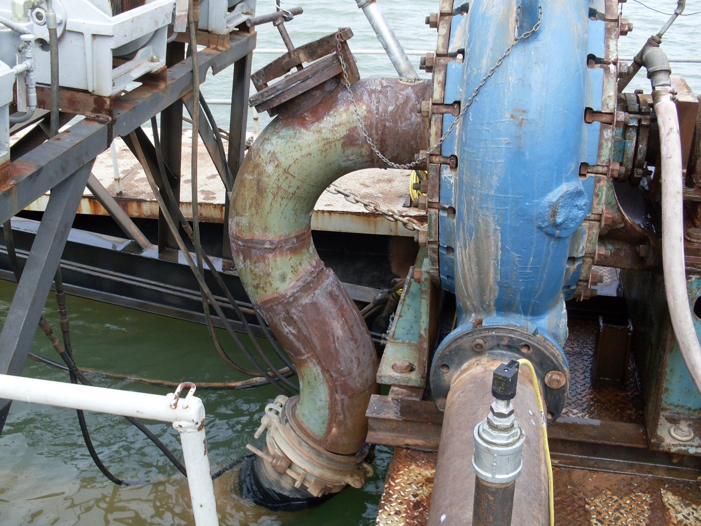
NOTE:
David sent the above picture which shows the artfully curved suction pipe that was connected to the inlet of his dredge pump and contributed to poor pump performance.
Another cause of wildly erratic vacuum is a damaged or worn out impeller.
Also a faulty packing gland will allow air to enter the pump. Any problems with the packing gland? What is the water pressure going into the gland?
Pump cavitation reduces production, damages the impeller and very often leads to a broken pump shaft. That hammering is caused by the impeller jumping up and down.
I would not be too concerned about lowering the pump if you are only dredging 25 feet deep. You should be able to pull a vacuum of 21-23 in Hg without cavitating if no air is entering the pump and with a CONVAC to enable constant production. That is enough vacuum to lift more solids into your pump than it can pump to discharge.
What is the discharge pressure when pumping solids? How long is the pipeline?
What diameter and SDR was the HDPE dredge pipe that failed?
Are your gravel pebbles and oversize rocks smooth and rounded or sharp and angular?
How long is your suction pipe?
I cannot help you with the cost of installing a CONVAC but I will tell you that it is not uncommon to find that a day lost to install it will be made up in the next four days of production with it in place—a 25 percent increase in production. Likewise, many times CONVAC has paid for itself in a couple of months of increased production. Keep in mind that an extra 50 or so tons per hour of solids going into your dredge pump will cost very little in extra energy to transport to the plant.
Imagine the CONVAC is already on your dredge. The vacuum is holding steady at about 19 inches and all the operator has to do is crowd the cutter into the material whenever the bypass valve trends toward going shut. During normal operation the valve should always be partially open and moving to maintain the proper vacuum. If it goes shut due to lack of pumpable solids at the suction inlet production will decrease.
Cave-ins? Usually the operator does nothing. They are welcome because they assure that there is ample pumpable solids available at the suction inlet. If the cutter stalls the operator needs to raise the suction inlet only far enough to free it to turn, not raise it out of the material bank.
All the while CONVAC is controlling the speed of the engine to maintain the velocity the selected rate.
Production continues without interruption at a rate no operator can achieve maneuvering the suction in an effort to maintain a certain vacuum.
Life is good for an operator who has a CONVAC in his toolbox to say nothing about the guy (guys) who benefit from the reduced production cost per ton
All the best,
________
Willard,
We’ve got the dredge back up and running today (Saturday) and I reduced the speed on the cutter to less than half. It actually performs quite nicely with a lot less bobbing up and down. The front end seems a little anchored down but it doesn’t appear its going to make any difference in production. Great advice.
It’s rare that I stop and clean the rocks out of the teeth. Usually this occurs at the end of the day and it’s just a couple of rocks. It only occurs during the day when there’s one in the teeth that’s causing the front end to bounce around a lot. I raise the ladder, stall the cutter, and go out there in the boat. MSHA does not allow operators to walk the ladder without a walkway and hand railing, and you never know when one of these guys will show up.
We use the METSO (Thomas) 10″x8″ with a 30″ 3-vane impeller. The pump was completely rebuilt about 1 yr. Ago. The veins at the eye of the impeller are showing some wear, but we’ve run impellers a lot longer than this.
I will change the packing and rework the tension bolts. Our water is pretty hard and rusts the bolts up quickly, making it hard to tighten the packing.
I need to change the seal in the fresh water pump. I’ve noticed that there is quite a bit of water leakage around the shaft. Air may be getting in through this and pushed into the packing gland.
Dredge pump discharge pressure is around 60 psi while pumping a good load of solids and the gland pressure is close to 80 psi. We have a booster pump about 900 feet downstream of the dredge. Exact same make/model pump powered with a VFD in a PID mode controlling a 200 HP electric motor.
The HDPE pipe that failed was a misapplication. It was 8″ with a 1/2″ wall thickness. If we had used 10″ HDPE, we would have gotten quite a bit more life out of it, but I’m not convinced it would have lasted near as long as steel. Any comments on the use of dredge hose? Seem like a waste of money?
Our gravel has a mix of shapes. Some of the flint is quite irregular, with some edges. Not sharp, but definitely not smooth or rounded. Most of the rocks are rounded in shape, but a good deal of them have a side that is broken.
The total length of the suction pipe is 37′, including the portion out of the water.
You’ve convinced me to go ahead and put the CONVAC system on now, and do the other stuff later when I’m caught up. It’s a hassle trying to keep production constant. It stresses me out from constantly moving, raising/lowering the ladder, and anticipating cave-ins. It puts the operator in a bad mood by the end of the day.
Thanks for the advice. I sincerely hope I’m not buggin you with this stuff, because I really appreciate your help.
________
David,
Glad to hear that the cutter slowdown seems to be working. It should take it a lot longer before it needs backring/backplate buildup.
I recommend 10” SDR 11 HDPE (8.8” ID) pipe fused into 250 to 350 foot long sections with flange end connections so you can bolt the pipe into one continuous length in the water. Use a 10′ or 12′ long flanged discharge hose between the dredge and the HDPE pipe. I would so away with pipe floats. The HDPE pipe will float at the surface when it is full of clear water and sink when it has material going through it. Once you have the CONVAC installed you will be able to control the velocity and keep it slow.
The dredge system is most efficient and productive when the velocity is maintained at just above the critical velocity, which is the rate at which solids commence to come to rest on the bottom of the pipe. Low velocity helps is minimize pump wear and energy consumption. Your gravel seems to be “normal” so I think that low velocity will give you satisfactory HDPE pipe life. Not having to mess with pipeline floats is a plus.
10′ t0 12′ lengths of discharge hose with Modified BIRF (Steel flanges built in) are useful:
- Between the dredge and floating pipeline.
- To make the 90 degree bend between the pump discharge and the pipe on deck.
- To connect 250 to 350 foot long lengths of floating steel pipeline.
- DO NOT use 3-4 foot pieces of discharge hose to connect floating sections of steel pipeline. Weld solid or use flanged bolt joints.
Coat the packing gland bolts with Never-Seize or grease and adjust the new packing (all five rings?) until the gland leaks a stream about the size of a lead pencil. It may need to be tightened frequently because pump cavitation likely will cause the shaft to wonder around in the packing gland and open up the small clearance between the packing and the shaft sleeve.
I believe that your CONVAC experience will improve your days in several ways. I am anxious to hear of your reaction once it is on and you have a few days to see what it can do for you.
All the best,
________
Willard,
Have you visited any other sand & gravel companies that use polypipe in a
correct application to dredge a course deposit with large gravel? I’m
curious as to how it’s wear life compares to that of steel. I need it to
last longer than steel or there’s no gain in using it.
I’m going to try a couple of 40 ft. sticks on the ground going to the
plant from shore and see how it wears.
I’ll let you know?
Thanks,
________
January 12, 2012
David,
Many dredgers with deposits similar to yours use HDPE pipe. The key to the successful use of HDPE pipe is to buy a wall thickness of about 1 inch and to keep the velocity low. In your case that would be 10″ SDR 11. (10.75″ pipe OD/SDR11 = 0.977″ wall thickness).
I am not sure about HDPE pipe lasting longer than steel, however, many of them feel that even if pipe life is shorter it is worth it to not have to deal with pipeline floats.
Best to test as you plan to do.
Regards,
________
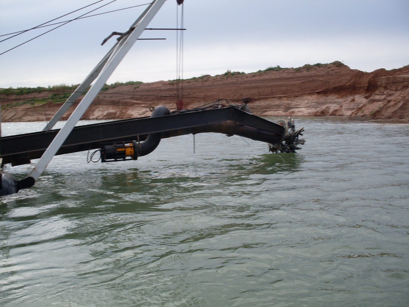
NOTE:
David’s CONVAC Linear Needle Valve can be seen connected to the bypass pipe on the underside of the ladder frame in the above photo. The bypass pipe loops upward from the valve and downward into the top of the suction pipe.
May 2012
Hey,
We installed the CONVAC system today and I met your grandson. Great kid.
Well it wasn’t an entirely successful day, and maybe you can shed some light onto the problem. I had mentioned in the past that we have a surging problem on the suction side of the pump. I have checked for air leaks and can’t find anything. I still haven’t replaced the worn-out seal in our water pump and am going to have one of the guys do that tomorrow. The seal is leaking water out and could possibly (not likely) be letting air in. I wouldn’t think it would hold its prime if it were sucking air through the worn seal.
The rapid swinging in the vacuum really plays havoc with the CONVAC system. It responds as if the pump is cavitating (which it is), and opens the bypass valve.
I also mentioned in a past email about the ridiculous suction pipe plumbing on the front of the pump and am wondering if this could be causing the vacuum swings. It may be the cause of the problem, but I vaguely remember that it didn’t always surge like this and the suction pipe had the same number of bends in it then – a full 120 deg. over and under and then about 45 deg. forward. Quite a mess.
We didn’t get to run very long due to a discharge pipe blowout so we weren’t able to really get into figuring out what was going on.
Yes, it’s laughable and ridiculous and was probably quite amusing for Bryce. But, it’s what I’m stuck with right now until I can change it.
What do you think? Have you ever seen a dredge with large bends in the suction pipe cause this kind of problem?
Later,
________
Dave,
Thanks for the good words about Bryce. We have high hopes for him.
Sorry you are still having problems with the pump.
The bends in the suction should not cause the surging problem you describe.
Each bend wastes vacuum with the result that there is less vacuum available to raise solids. As long as not air can enter the system, the only indication of a series of bends in the suction would be an abnormally high clear water vacuum.
A problem often occurs if there is a high point in the suction pipe where an air bubble can form. As the vacuum increases the bubble expands to interfere with flow through the pipe to the pump. This problem usually prevents the pump from priming. Do you have a high point? A bubble entering the water-filled suction pipe inlet should flow all the way up and into the pump even if water is not flowing through the system.
Another problem which displays various symptoms is a loose liner tube in the suction sleeve. Usually this problem shows up when vacuum reaches a certain point and then goes to the maximum and cavitation occurs. The pump may lose prime or perhaps the problem subsides when the vacuum is reduced. Sometimes the only way to reduce the vacuum is to backwash the pump. Usually, this situation increases in severity as the liner progressively loosens. Check by installing a vacuum gauge on the suction inlet side of the sleeve and compare its readings with your operating vacuum gauge. The new gauge will always have a lower reading because it is tapped into the pipe at a point that is lower and closer to the suction inlet. The two gauges will react in like fashion if there is no problem with the sleeve. A high vacuum in the cab and little or no vacuum on the lower gauge indicates that the sleeve tube is collapsing as vacuum increases.
Surging is a 95% sure sign that air is getting into the system. Pump operation will be smooth if the pump is in good condition and pumping pure liquid.
Keep me informed.
________
Dave,
Thanks for the pictures.
I need more time to think about your situation, however, one thing does stand out in the pictures. Burn a 3/4″ hole in the top of that 180 degree weld bend in the line from the CONVAC valve to the suction pipe. The hole will allow air to escape. I do not know whether this air is a significant problem or not but it could be.
More later.
_________
Willard,
We’re still trying to track down the cause of the surging on our dredge. If it is an air leak, I can’t find it. We’ve used three cans of shaving cream and coated every welded joint, mated component, and hose connection from the waterline up. I’ve changed the seal in the water pump and made sure the flow from it is bubble free. Still nothing.
I won’t be able to use the CONVAC system as it was designed for until I fix this stupid surging problem.
Here’s a perfect example of what poorboying and throwing crap together will get you. I’m stuck with this piece of junk dredge until I can get enough time to make the changes to it. Until then, the trucks do not stop.
I need a vacation.
I did try to run the system on AUTO and set the vac setpoint to a low 18 in. Hg just to see how it works. The surging is not near as bad at the lower vacuum. As the vacuum increased to around 18, the valve opened a little. OK so far. Then the vacuum increased a little more and the valve opened further. Still OK I guess until you start watching the velocity. As the vacuum approached 22 in., the valve position was at 34% and the velocity had climbed substantially. Acts just like a rock stuck in the suction mouth. Did I place the valve too far downstream of the suction mouth? The cutter was buried in material and the solids percentage obviously went down. Not a good thing for production. I noticed after raising the suction out of the material, that it took some time for the vacuum to decrease, the valve to shut, and the suction to clear.
I have attached some pictures to show the plumbing on the front of the pump as well as the position of the valve on the ladder. They may be of help or they may be amusing. Also included is a picture of the solids bank showing the material we’re dredging and the back ring wear problem on our cutterhead.
I forgot to let you know that the polypipe you recommended has been in the piping system since Feb. 2, and is still showing no signs of rippling on the outside bottom surface. Great. Need to break it apart soon and check for wear.
Thanks for your help and I’ll keep you informed.
______________
May 16, 2012
Dave,
It appears that you are suffering from a plugged suction due to low velocity. This situation is not uncommon on dredges that do not have bypass systems and the solution is to increase the operating velocity or install a smaller suction pipe.
In your case it likely is due to the CONVAC water inlet pipe being located too far from the suction inlet. Our rule of thumb is about 10 percent of the suction pipe length and there have been instances where that was too far away.
On the other hand, if the inlet is too close to the suction inlet the intake of solids cannot be controlled because the bypass water picks up solids in excess of the desired rate.
There is no rigid rule.
We have built new dredges with suction pipe one size smaller from the bypass water inlet location to the suction inlet and they work very well.
Looking at the photo of your ladder the bypass water inlet appears to be 10 or more feet from the suction inlet. You might consider running a straight pipe from the Linear Needle Valve and 90 degree elbow into the side of the suction pipe near the point where it bend down under the cutter gearbox. We recommend that the bypass inlet into the suction pipe be on top, however, going into the side of the suction pipe works as well.
I will say that your suction pipe arrangement might well qualify for entry in the art section of the county fair.
Glad to hear that the HDPE pipe seems to be performing well. Consider rotating it before the wall thins to the point of failure.
Backring wear is a maintenance issue that lacks a sure cure. Give thought to cutter speed. Every revolution causes wear so slowing the cutter to a speed just fast enough to assure the desired rate of production will extend the time between rebuilds.
Hope this helps.
All the best.
Keep me informed.
__________________
|
Willard, Thanks for getting back to me. I had a good laugh about your comment on our suction pipe. We kinda figured we put the water inlet for the bypass too far back from the suction mouth. My son questioned my choice of location when we were installing it. Should have listened to him. I’ll be rerouting the water intake as you suggested and keep the needle valve where it is. Just as soon as I can get ahead of the trucks and get a longer suction hose, we will be changing the plumbing on the front of the pump. Eventually (hopefully in the near future), we will be lowering the pump to water level and adding floatation onto the back of the dredge so that we can scoot the pump and engine back a bit. It will be much easier and safer to work on the pump having it behind a front wall and a floor under us. We already have everything fabricated for this and stored in our shop. Thanks again for your help and I’ll get back with you when we get some things changed around and the CONVAC system up and running. _____________ |
May 17, 2012
Dave,
Had another thought.
I can’t tell from the photo but it appears that if you remove the cutter basket the suction pipe termination is the end of a 10” pipe.
If that is the case the problem of low velocity in the suction pipe can be partially solved by shoving a section of 8” pipe into the 10” suction pipe and securing it so that it cannot slide out to stall the cutter basket. The end of the 8” pipe should stop just short of the elbow in the 10” suction pipe so it cannot enter and partially block the 10” elbow. Other than retaining the 8” pipe it does not have to sealed off in anyway. The annular opening between the 8 & 10” pipes will seal shut with fines.
If that much of the suction pipe has a high velocity the remaining section of 10” low velocity pipeline between the end of the 8” liner pipe and the Linear Needle Valve inlet will be shortened considerably and there may be enough turbulence to prevent plugging in that portion of the suction pipe.
_____________
May 21, 2012
Willard,
Got your message. Just as soon as I get a new and longer suction hose to get rid of the contraption on the front of the pump, I’ll move the water inlet on the bypass valve forward and try it again before I have to install the smaller suction pipe. I really think it will be OK with the 10″ pipe if I put the water inlet closer to the suction mouth. If not, I’ll insert the 8″ pipe up to the water inlet.
If I remember correctly, the surging problem started when I replaced the old worn-out contraption on the suction side of the pump with a new and improved contraption. More external wear plates, internal hardfacing, and really sharp bends. Great idea.
Should be getting a new suction hose in a week or so. Until then, the battle continues.
I’ll let you know the results then.
Thanks,
______________________
May 24, 2012
Dave,
I suggested the 8” pipe insert as a quick partial fix until you get time to move the inlet further down the suction pipe. I think it would improve the situation, but not cure it. If it turns out that it cures the problems I would consider it to be a permanent fix and not move the inlet location.
_________________
June 25
Hi Willard,
Hope everything is well with you.
Just thought I’d let you know we’re currently changing the suction on our dredge and moving the water inlet forward on the bypass valve. That contraption on the front of the pump is completely worn out and will be replaced with a 20 foot suction hose. I’ll send you some pictures to show you where we placed the water inlet.
We should have it running by Tuesday evening. I’ll let you know how it goes.
Later,
_________________
July 2012
Hi Willard,
I really wish I could figure out why this pump is surging. The entire suction system has been replaced from the pump all the way to the suction mouth, and it still surges and cavitates. I’m afraid to turn the CONVAC system to auto mode with this instability.
The impeller has less than a few hundred hours on it and very little wear, so I know the cavitation is not because it’s worn out. The packing is good and has adequate water pressure (15 psi > pump discharge).
Priming the pump is done with a flap valve in the suction pipe, which allows me to fill the pump and suction piping with water under a slight pressure. No leaks. Everything is air tight.
I checked the VFD on the booster pump thinking it may be having trouble converging on the 15 psi suction inlet pressure and overshooting/undershooting. I turned off the PID mode and set the booster pump rpm constant by adjusting the frequency. Dredge pump still surging.
Here are some numbers that may help.
Clear water vacuum is 10.4 in. Hg. Suction pipe is 38 feet long. Dredge depth is around 24-25 feet. Centerline of suction on pump is elevated 5 feet off the water. Clear water velocity is 21 feet/sec. Pump rpm is approx. 700. Clear water discharge pressure bounces around between 58 and 62 psi. During dredging, I try to maintain a suction vacuum around 23 in. Hg. Velocity runs around 14-15 feet/sec for average material and around 13 for course stuff. The discharge pressure fluctuates around 55 to 70 psi with a steady, rythmic, irritating hammering of cavitation. Before installing the CONVAC display, I read the vacuum with a manual gauge and noticed a wide swing in the reading. In fact, when it’s really bad, you can feel a slight positive pressure in the line when it swings to the lowest point.
The only thing I know left to do is take the pump completely apart and see if there’s anything obviously wrong.
This surging problem is beyond me and may require a pump hydraulic expert to figure it out. What do you think?
I don’t know what to do next.
Any help would be appreciated.
Thanks,
_______________
July 6, 2012
Dave,
I have run your numbers in my Dredge Performance spreadsheet and I can’t make sense of the results.
You say your clear water vacuum of 10.4 and my computer agrees showing a vacuum of 11” with a velocity of 21 feet per second in your system. I always question clear water velocity because doppler type meters are seldom accurate unless there are solids in the flow and I also have some doubt that you can actually create a velocity that high in your dredge system.
My program shows that the clear-water vacuum should be about 8” if you maintain the velocity at about 14 fps and that is about what I would expect.
Okay, now the pumping numbers.
I calculate that your dredge should be able to pump 300 tph of solids at a velocity of 14 fps and a vacuum of about 18”. In your correspondence you consistently mention high vacuum–high compared to the computer projections.
I know that the computer is not a real dredge, however, I recorded numbers off of every dredge I ever visited and ran them on my program to see what kind of a match I could get. I wrote my program using published mathematical precepts that apply to pipeline transport. Turner and Houston were keen students of dredge operation and published books on their findings. I then tweaked my program over time in an effort to get it to reflect how a real dredge system could be expected to perform.
I have a lot of confidence in these projections and it points to a restriction in your suction pipe. You mention a flap valve in the suction and I suspect that it is the dirty dog that is doin you wrong. I recommend you take the flap valve out of your suction and find another way to prime the pump. I have some ideas on how to do that.
All the best,
____________
Willard,
Got your numbers. Thanks a bunch for running ours through your program. It seems we have some conflicting results which, like you said, may be pointing to some restriction in the suction. However, the clear water numbers seem to match which is puzzling. It seems a restriction should show up at every point in the pumping process.
Unless I’ve really underestimated how much fine sand is going to the waste pile under the cyclone, there’s no way I’m doing 300 tph at 18 in Hg. and 14 fps. I wish I was. With the pump speed I quoted earlier, a vacuum of 18 in Hg. would produce a velocity around 16.5 to 17 fps and much reduced production on our dredge. I’d have to decrease the pump speed to get 14 fps. Just thought this may be useful data.
Now, about the flap valve. I hate it, but is was a cheap and easy way to prime the pump. After engaging the clutch and establishing full flow, I lock the flap valve into the open position so I know it’s not falling down and bouncing around into the free stream. The flap valve is housed in a box that’s about an 18″ cube with an inlet and outlet the same size as the suction (10 3/4 OD). Maybe there’s some kind of funky fluid dynamics going on in there that may be causing the surging. I don’t know, but it’s worth getting rid of and trying.
You mentioned some ways to prime the pump without a flap valve. I’m interested in using one you recommend.
Sorry I’m so windy, but I also wanted to let you know that I flipped the CONVAC over to auto now that we moved the water inlet as you recommended. It’s centered about 32 inches downstream of the suction mouth on the side of the suction pipe. I’ve been running it for a couple of days and am smiling again. Very impressive piece of hardware. I had to turn the vacuum sensitivity down to 12 and the close speed to 8 (I think) so it will work with the surging problem. It has a little trouble holding the vacuum at the setpoint during some cave-ins, but as soon as I get the surging problem fixed, I’ll monkey with the sensitivity/open/close speed and turn the cavitation feature on and see if this helps.
After all is operational, I’ve got another dredge that needs one of these.
Thanks again for your help and look forward to hearing back from you.
____________
July 9, 2012
Dave,
Willardsays’ “Dredge Pump Priming” covers that subject pretty well.
Immersing a short section of the discharge pipe immediately back of the dredge is my favorite way to seal the pipe because it works every time, is inexpensive to accomplish and has no moving parts.
Connect the suction port of an eductor to the valve you have in the port at the top of your pump shell, connect the inlet port of the eductor to your service water supply and direct the outlet port of the eductor overboard. Shut off the service water to the cutterhead and direct all the flow to the eductor and the packing gland. The eductor pulls and the packing water pushes—win-win situation.
Priming the dredge pump take place when you lower the suction pipe into the water, open the valve on top of the pump shell and direct service water through the eductor. The eductor will evacuate the air in the pump shell and cause it to fill with water—if no air can enter the “sealed” portion of the dredge system. The eductor discharge will change when it runs out of air and starts evacuating water. You will also see the vacuum increase. Experimenting will tell you how much vacuum you need before you commence running the pump. Slow pump start speed is good as opposed to goosing it. IF NO AIR enters the system while priming is in progress you should prime up 5 minutes or so.
A 1.5-inch bronze eductor is $565 FOB West Liberty, Iowa and it usually will ship in two or three days.
Further reflection on your dredge system. You are pumping 900 feet through 8” ID pipe to a booster which is set to maintain an inlet pressure of about 15 psi. I suggest that 900 feet is too far away. At that distance the dredge pump has to do a lot of work and the booster could relieve it of some of the load if it were located closer to the dredge.
How much pipe is there between the booster and the discharge point?
My goal is to help you pump 300 tph at 18 to 20 inches of vacuum with a velocity of about 12 fps and the pump running at about 800 rpm. The CONVAC will perform most of the operating chores while you tweak its settings and enjoy life even more.
All the best,
__________
Willard,
Thanks for your reply.
I’ll call your guys tomorrow and get an eductor coming.
The booster is located on the water and has approximately 500 feet of discharge pipe and 50-55 feet of vertical head. It’s powered by a 200 hp electric motor. Data from the VFD I/O indicates it’s 75% full load when running at our best, so it could be floated a little closer to the dredge. I don’t have much wiggle room here and could overload the VFD if I push it too much. Should have put 300 hp on it.
My days are much better now. It’s such a relief to not have to continuously fight to maintain a decent suction vacuum. I’m looking forward to getting the cavitation fixed and going to fully operational.
More news. The Polypipe has now been in service for 5 months. Drilled a hole just downstream of a lower section to measure the wear and found it to be only 0.2 inches. Not bad at all. Just a little over 3/16 of an inch for 5 total months of dredging. I consider this acceptable and will order Polypipe and get rid of the steel pipe and those irritating floats. Got a quote of 15.32 a foot delivered price for 10 SDR 11.
Later,
_________
July 2012
Dave,
Glad to hear that you are making progress.
I ran your dredge system with a total of 1500 feet of 8” steel pipe and 56 feet of lift. A total of about 300 horsepower (dredge + booster) would be required to pump 300 tph of sand at velocity of 13.5 fps.
Always keep in mind that production on the computer assumes constant production at a uniform rate. NO interruptions. High production cannot be obtained unless the rate of production is continuously maintained and precisely regulated. CONVAC makes that happen as long as an excess supply of pumpable solids is always present at the suction inlet. Precise control of production will enable you to confidently experiment with slowing the velocity down to perhaps 12 or 12.5 fps. Slowing from 13.5 fps to 12.5 fps would reduce the horsepower required to about 270—a 10 percent reduction!
HDPE pipe floats when it is full of clear water with freeboard equal to about the thickness of the pipe wall. HDPE pipe will automatically prevent air from entering your pump when using an eductor to prime.
Mark the HDPE pipe segments and plan on rotating it 120 degrees when wall thickness (at the bottom) gets down to about 5/8”. At that thickness the pressure rating falls to about 90 psi, down from the 150psi rating when it was new.
Leave the booster where it is for the time being. Once the surging is eliminated and the CONVAC can perform its magic we can take another look at the numbers and see if there is any advantage to moving it.
Dredge on!
__________
September 2012
Willard,
Hope all is well with you.
We started dredging through the Polypipe today. I was so hoping we would be able to use it without floats, but when it sinks to the bottom it settles into the silt and anchors the dredge (the silt is from our waste that returns to the lake). I can’t move forward or backward and only to each side a little. Dragging it through the silt is impossible. The swing winches haul in line and lift the front of the dredge up while the rear is anchored to the bottom. The only way to advance or backup is to lift the suction until the poly floats and then move.
I have to continue running this way until I build enough of a stockpile to allow some time to install floats under the poly. I’m not going to float the entire line, just about a 300 foot loop of it. The floats are from the steel pipe that is still in the lake.
It’s a never ending battle, but I hope we’re moving in the right direction.
I haven’t had the time to install the eductor and remove the flap valve yet. Soon.
I’m also working with Bryce to fix the CONVAC system. I think I’ve got a bad end on a cable coming from the all-weather box outside. Something minor.
Until next time,
_____________
February 2013
Willard,
Have you ever used or heard of using a diaphragm seal/transducer directly on the suction pipe of the pump for measuring vacuum for your convac system?
If this would work it would eliminate the vacuum tube and possible plugging.
It seems to me that you would get a better reading on vacuum than having a standpipe with a tube connected to a transducer located in an elevated position. Each time the standpipe/tube is cleared, a lower reading will show on the vacuum display for a while. I assume this is because there is usually water/slurry that gradually percolates into the standpipe and tube that is actually increasing the vacuum on the transducer due to the head of the water column. For a suction-side-limited dredge (like ours) this could help with production by providing a more accurate reading for controlling the bypass valve position.
Any thoughts?
Thanks,
__________
Dave,
Good to hear from you again.
We have been looking for the answer to the problem you outline for over thirty years and we feel that we are are getting closer to the solution.
It is a problem on hullpump dredges such as yours and an even greater problem on ladderpump dredges.
Locating the transducer directly on the suction pipe port seems ideal, except that subjecting a transducer to abrasive particles hastens its destruction and frustrates is function. Off-the-shelf gauge snubbers are relatively inexpensive and available to do this job, however, they soon pack with sand and fail.
The major problem is pressure spikes. Occasionally, after the suction pipe has choked off and caused a very high vacuum, the choke suddenly breaks loose and causes a pressure spike that breaks the transducer. Transducers have a limited capacity to deal with pressures that are significantly outside their design operating range and vacuum transducers have little tolerance for high positive pressure.
Another problem with putting the transducer directly on the suction pipe is that of flutter. Often the vacuum is not stable, it fluctuates rapidly and a sensitive gauge such as a transducer will generate a flurry of readings that are not pleasant to monitor. The tubing between the tap on the suction pipe and the transducer serves to cushion pressure spikes and dampen flutter so it useful in that regard.
We are testing a snubber that will work on both hullpump and ladderpump suction pipes. It shows promise to cushion against pressure spikes, dampen flutter, self-clean, be plug resistant, work on vacuum and discharge pipes and be easy to service.
We will keep you informed.
Meanwhile, how are things going?
You first wrote me 13 months ago about your backring problem and we have since batted nearly 9,000 words back and forth. I hope you have profited as a result.
To get back the the backring question. We are experimenting with Ford Steel white iron products and it seem nearly immune to wear. Google for it and see what you think. We have not used it on a cutterhead however we will use some of it in the two linear cutters we are currently building.
As ever,
___________
February 2013
Willard,
Thanks for getting back with me. Sounds like your working towards a solution on the transducer problem. If you have success with the snubber, let me know and I’ll try it on our dredge.
Everything else is going as usual. Very busy. The oil and gas industry in our area is booming and generating a bunch of business for aggregates as well as our concrete business.
We’re in some pretty tough digging now in our deposit. Some of the worst I’ve seen since we started this operation 15 yrs ago. Lots of very packed gravel and finer sand. About all we can do is swing back and forth and cut it loose gradually. It will not feed well at all. The cutter just digs holes down when you lower it and creates massive walls on either side that cave in and bury the ladder, stalling the cutter. The cavitation feature on the convac system is having trouble keeping up. Smaller cave-ins are OK, big cave-ins are not so good. I suspect the clog is reaching all the way up to the bypass inlet in the suction pipe and not allowing any clear water to enter. May need to do something about this. Hopefully it’s just a seem we have to get through.
As for the backring problem, we are still rebuilding it as we have in the past by welding. It’s difficult to keep up with and sometimes the gap gets too big and begins to bind and slow the cutter to the point that production is severely hampered.
I did check out the website for Ford Steel and am considering using the chocky bars for the inside of the backring. I’ll need to place them on the opposing side of the back plate as well. With the mild steel backing material, I’ll be able to form them around the ring and back plate.
Thanks for the info. I’ll let you know how it works out.
Later,
_____________
March 2, 2013
Willard,
We’re having some difficulty getting the CONVAC system to work as well as I’m sure it should. Adjusting the parameters by trial-and-error method is just not getting us there. It would help immensely if we had some understanding as to how each of the parameters effects the performance of the system. Is there any documentation or operators manual that could provide some help? After installation we got zip for operators instructions or documentation. I’ve emailed the office and got no response.
The system is not catching all the cavitation events because the valve appears to not be opening fast enough. When we adjust the cavitation variables to a set of values that seem to help, then the valve is open too much of the time and we lose significant production. We can’t figure out what direction to move the variables to because we can’t clearly determine how they are affecting the system.
It also has some trouble maintaining the vacuum and velocity above a set-point. It allows both to drift too far into the red zone and then the valve opens way too much and overcompensates.
We still don’t know if we have positioned the water inlet correctly. We may still yet need to move it.
I’m at a loss as to how to get it to work better since I don’t know what to adjust.
Some help would be appreciated.
Thanks,
_________
March 2013
Dave,
Sorry to hear that you still have some glitches. Scott assures me that he will be addressing your concerns.
Keep me informed.
____________
October 2013
Willard,
Just wanted to thank you again for all the helpful advice you’ve provided. Dredge is running well. I got rid of the flap valve using the eductor and am very pleased at how little time it takes to prime. Should’ve emailed you a long time ago and saved a bunch of work.
I’ve also installed a water-gun and am extremely pleased with the results. The feed to the cutter is much more stable, and I have been able to significantly increase the average solids intake. It also eliminated the abrupt cavitation problems with severe cave-ins. Now the CONVAC is able to keep up with the smaller cavitation events.
The nozzles are located above and behind the top of the cutter backring far enough to stay out of the way but close enough for the water stream to impact the material bank and help loosen it and induce smaller cave-ins.
Polypipe is performing very well. Thanks for recommending it.
I can’t possibly imagine going back to dredging without a CONVAC system. It has done wonders for my mental health.
Thanks again,
_________
Dave,
Thank you for getting my day off to a great start with your kind words.
I get a lot of satisfaction from providing information that enables dredgers to increase production and productivity and profits. Your testimony is frosting on my cake.
Thank you again.
Contact WillardSays.com with questions, comment or criticism.